
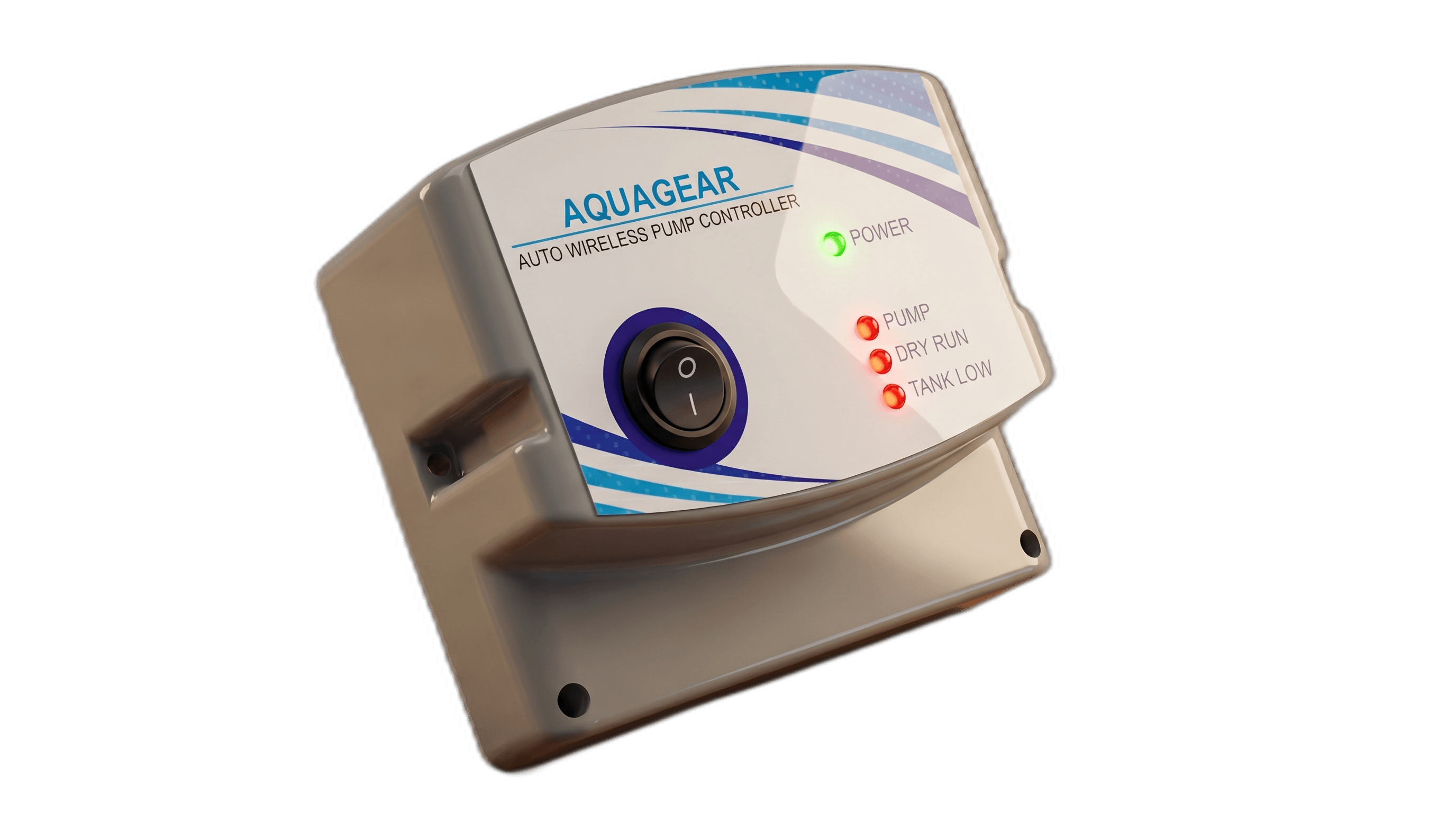
Why Choose AGUAGEAR?
Key Features & Benefits
12 reasons AGUAGEAR is the smartest choice for your water management.
System Operation
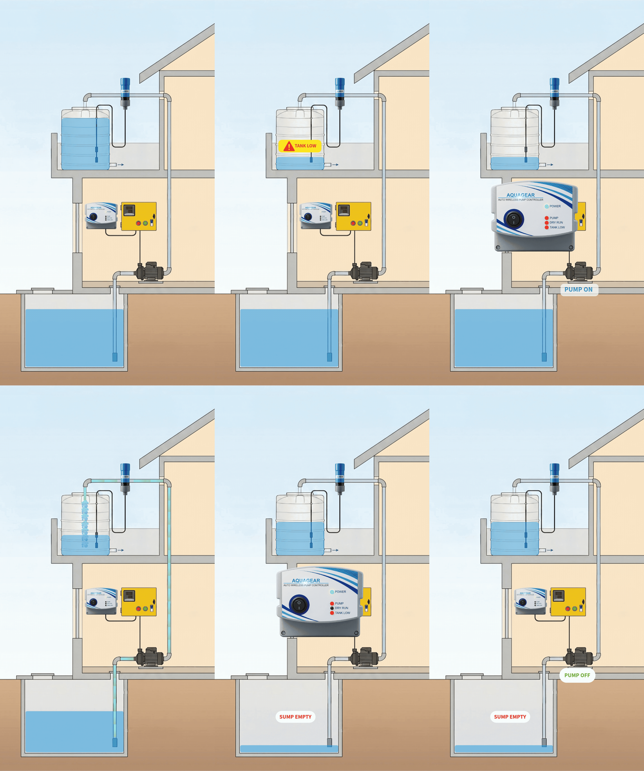
How AGUAGEAR Works
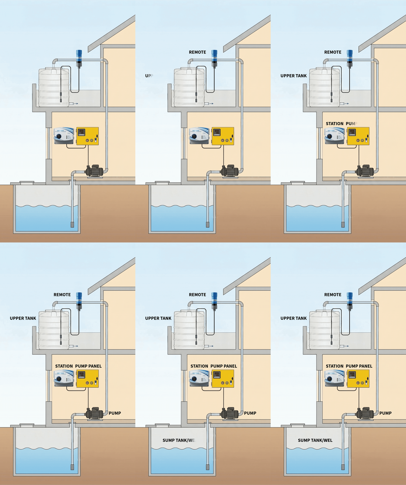
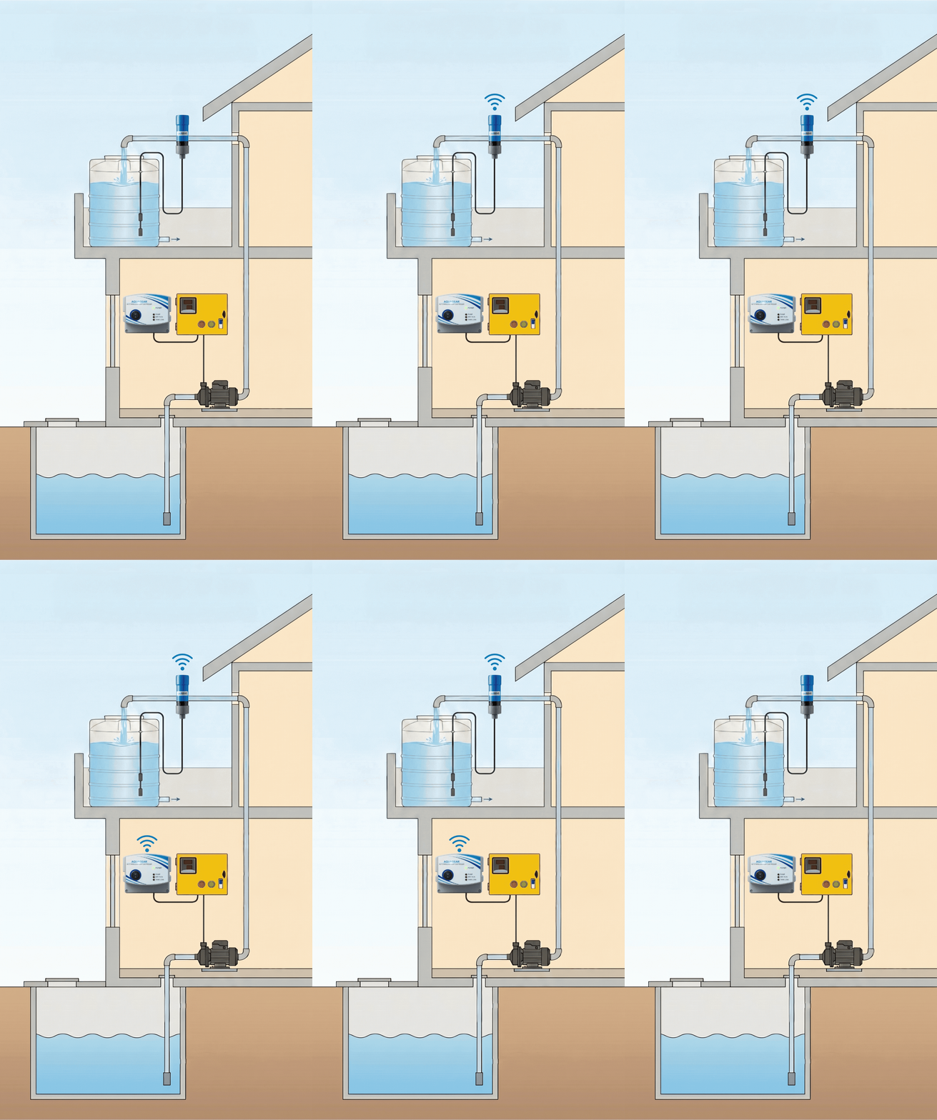
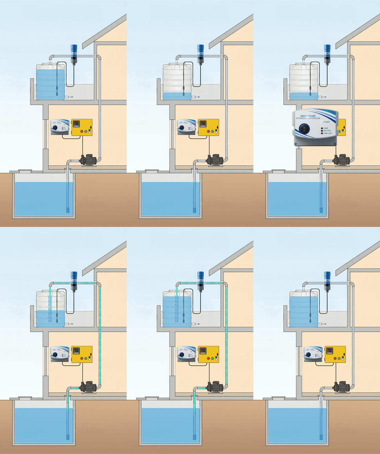
Seamless, smart, and secure automation using a STATION + REMOTE architecture.
Technical Specifications
Installation & Wiring Guide
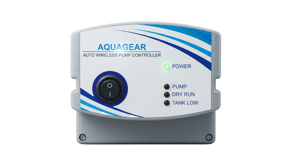
STATION UNIT OVERVIEW
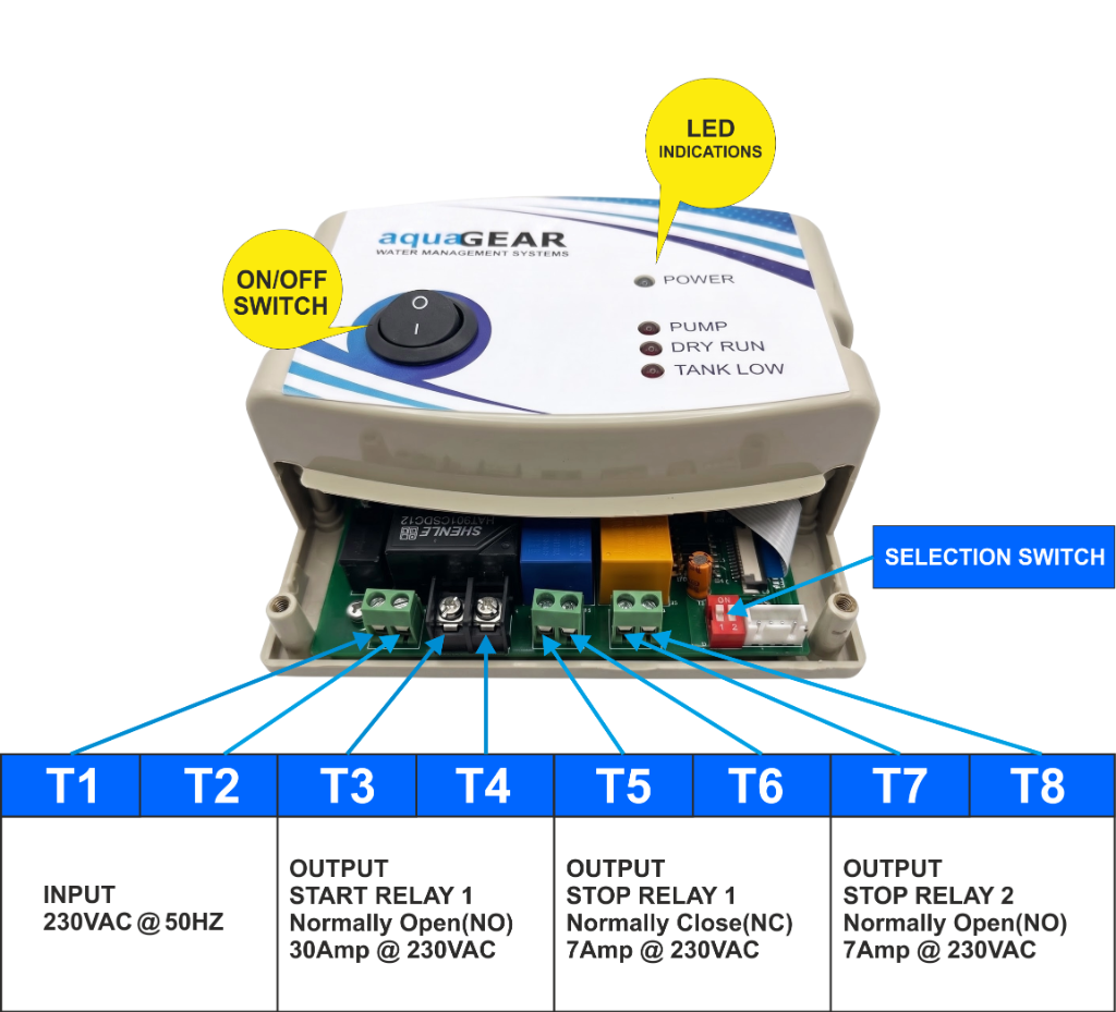
Terminal Ratings & Specifications Reference
| Terminals | Function | Rating / State | Application |
|---|---|---|---|
| T1 & T2 | Mains Power Supply | 230V AC, 50Hz | Provides operating electricity to the Station unit |
| T3 & T4 | Start Relay 1 | Normally Open (NO), 30A | Direct pump control or Pump panel START button pulse trigger |
| T5 & T6 | Stop Relay | Normally Closed (NC), 7A | Pump panel STOP button circuit |
| T7 & T8 | Start Relay 2 | Normally Open (NO), 7A | Pump panel START button Auxilary pulse trigger |
REMOTE & TANK SENSORS
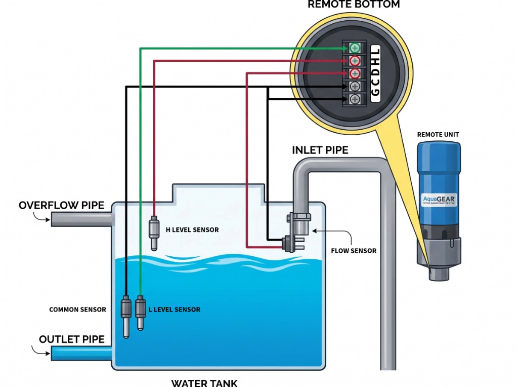
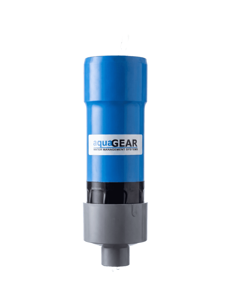
Tank Sensor Probe Terminals (G, C, D, H, L)
Internal supply ground. Connect to C (Common) to activate the Remote Unit.
Reference probe immersed at the bottom of the water tank.
Installed on the tank inlet pipe to verify active inflow and protect against malfunctions.
Installed near the upper tank rim (just below overflow pipe) to shut off pumping when full.
Placed near the lower water threshold (above the outlet pipe) to trigger automatic pump startup.
Sensor Installation Steps:
- Mount the Remote Unit vertically near the tank opening using the provided bracket.
- Drop the C (Common) reference probe down to the bottom of the tank so it remains perpetually immersed.
- Suspend the L (Low) probe at your desired minimum refill level (typically 20%–25% from bottom).
- Suspend the H (High) probe 2–3 inches below the tank overflow outlet pipe.
- Attach the D (Dry-Run) sensor directly inside or at the mouth of the tank inlet pipe.
- Short G (Ground) and C (Common) to activate the Remote Unit.
Dual-Tank Automation: Extra Sump Remote Unit Integration
For homes, apartments, and buildings with an Underground Sump Tank supplying an Overhead Tank (OHT), you can pair an optional secondary AquaGear Remote Unit at the sump tank:
- Wireless Sump Monitoring: The extra Sump Remote checks water levels in the underground sump and transmits live status to the Station controller without any trenches or cables.
- Intelligent Source Interlock: The Station unit only turns ON the pump when the Overhead Tank requires water and the Sump Tank has sufficient water level.
TYPE 1: DUAL POLE (DP) SWITCH
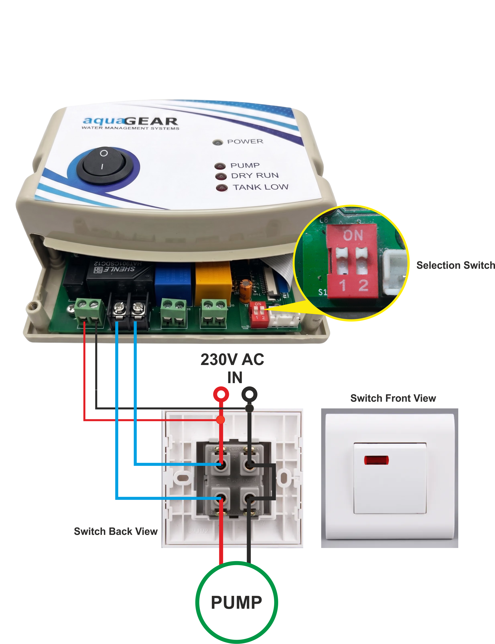
For domestic pumps operated with a standard ON/OFF DP switch. The built-in 30A Start Relay 1 (T3, T4) directly handles the motor load. Well-suited for 0.5 HP, 1.0 HP, and 1.5 HP pumps.
Wiring Connections:
- Connect 230V AC Mains Phase (P) from the Dual Pole (DP) switch input terminal (Phase line entry point) to the Station unit T1 terminal.
- Connect 230V AC Mains Neutral (N) from the Dual Pole (DP) switch input terminal (Neutral line entry point) to the Station unit T2 terminal, and common it to the Pump Neutral (short the switch input Neutral and output Neutral).
- Make a parallel connection across the Dual Pole (DP) switch using terminals T3 & T4: connect Station terminal T3 (Start Relay 1) to the switch Phase line output point (the line going to the pump), and connect Station terminal T4 (Start Relay 1) to the switch Phase line input point (the line from mains distribution).
- Ensure Selection Switches 1 and 2 are both in the ON position, then turn ON the device ON/OFF switch.
TYPE 2: DOL STARTER (DIRECT-ON-LINE)
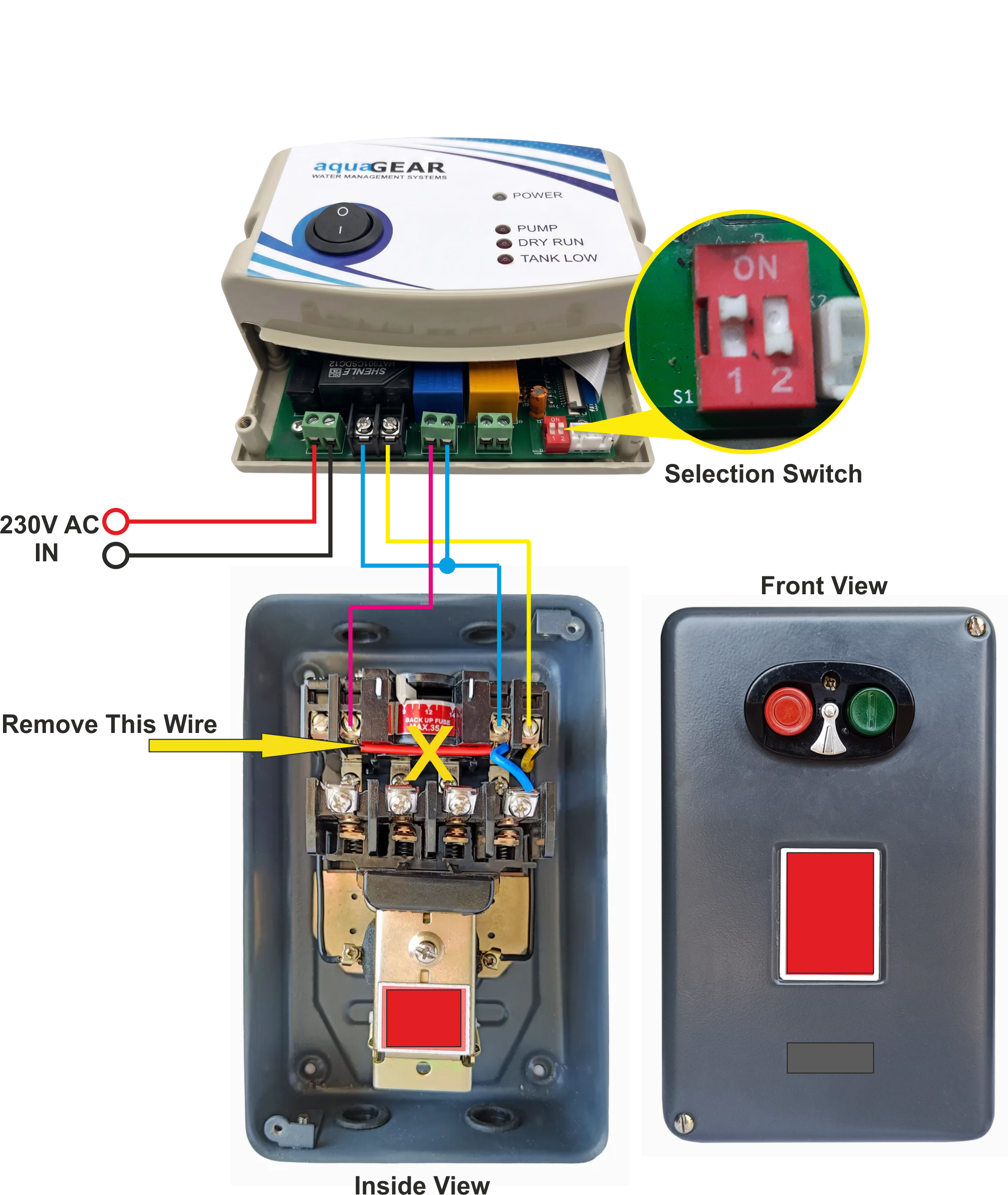
In 3-Phase DOL Starter configurations, a Single Phase Preventer (SPP) must be installed in series with the starter control circuit to protect the motor against single phasing, phase reversal, and phase unbalance.
Disconnect the jumper wire between the contactor auxiliary terminal and coil (marked with a Yellow Arrow / Red X in diagram) for WPC pulse control.
Wiring Connections:
- Connect 230V AC Mains supply to Station T1 (Phase) and T2 (Neutral) terminals to power the unit.
- Ensure a Single Phase Preventer (SPP) is integrated into the starter control circuit for comprehensive 3-phase motor protection.
- Remove the internal auxiliary hold-in loop wire from the starter contactor coil (marked with Yellow Arrow / Red X).
- Connect Station Stop Relay terminals T5 & T6 (Normally Closed - NC, 7A) in series with the starter contactor STOP button / coil circuit.
- Connect Station Start Relay 1 terminals T3 & T4 (Normally Open - NO, 30A) in parallel across the Green START button contacts (or auxiliary NO holding terminals).
- Verify Selection switch setting: Switch 1 is ON, Switch 2 is OFF.
TYPE 3: MULTI CAPACITOR SUBMERSIBLE PANEL
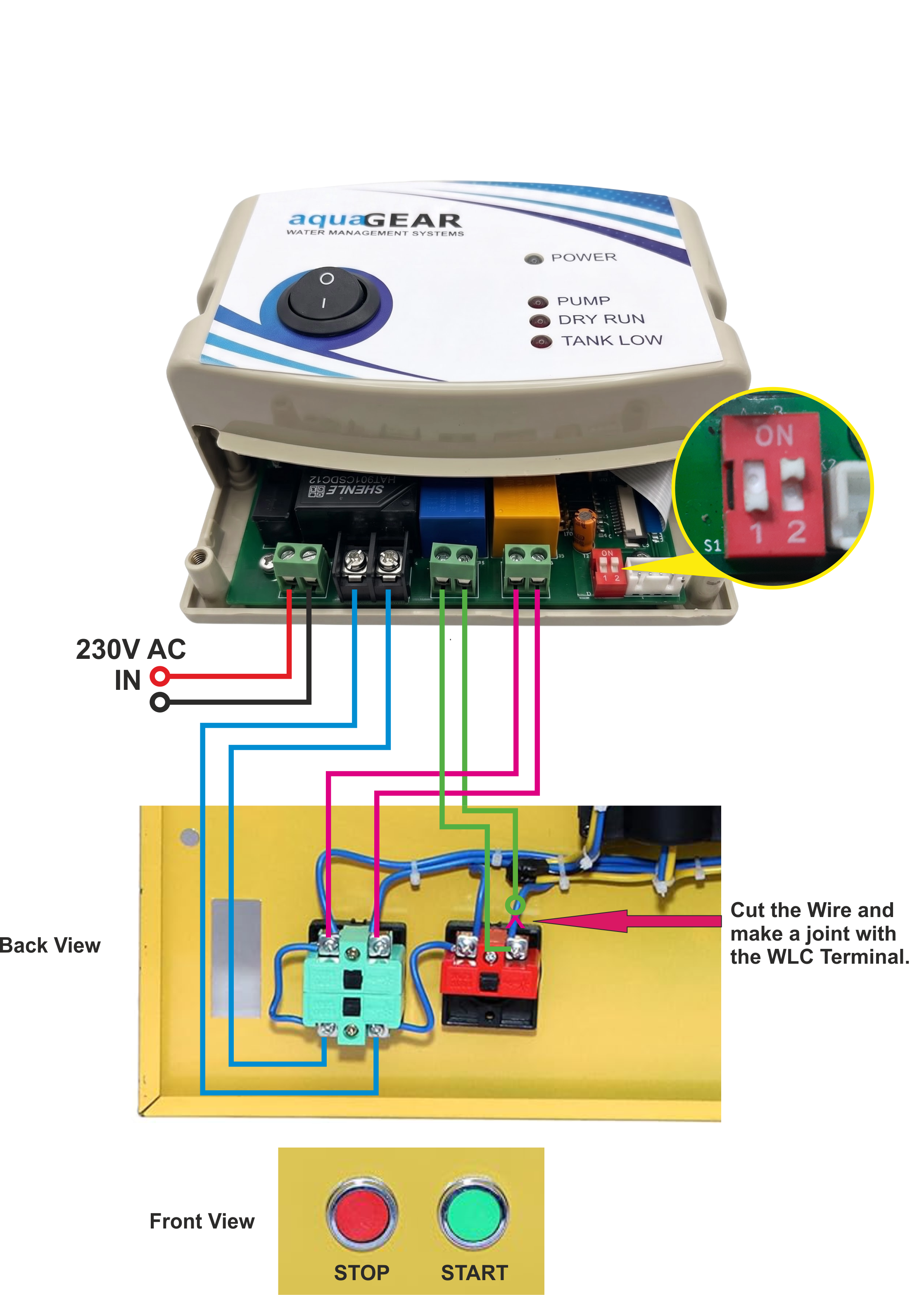
Cut the internal wire behind the Stop push button and connect Station Stop Relay (T5, T6 - Normally Closed, 7A) in series across the cut joint to enable automatic shut-off.
Wiring Connections:
- Connect 230V AC Mains supply to Station T1 (Phase) and T2 (Neutral) terminals to power the unit.
- Cut the line leading into the Red STOP button and connect Station Stop Relay terminals T5 & T6 (Normally Closed - NC, 7A) in series across the cut joint.
- Connect Station Start Relay 1 terminals T3 & T4 (Normally Open - NO, 30A) in parallel across the Green START push button contacts.
- If auxiliary start triggering is used, connect Station Start Relay 2 terminals T7 & T8 (Normally Open - NO, 7A) across the auxiliary start contacts.
- Confirm Selection switch configuration: Switch 1 is OFF, Switch 2 is ON.
TYPE 4: SINGLE CAPACITOR MCB TYPE SUBMERSIBLE PANEL
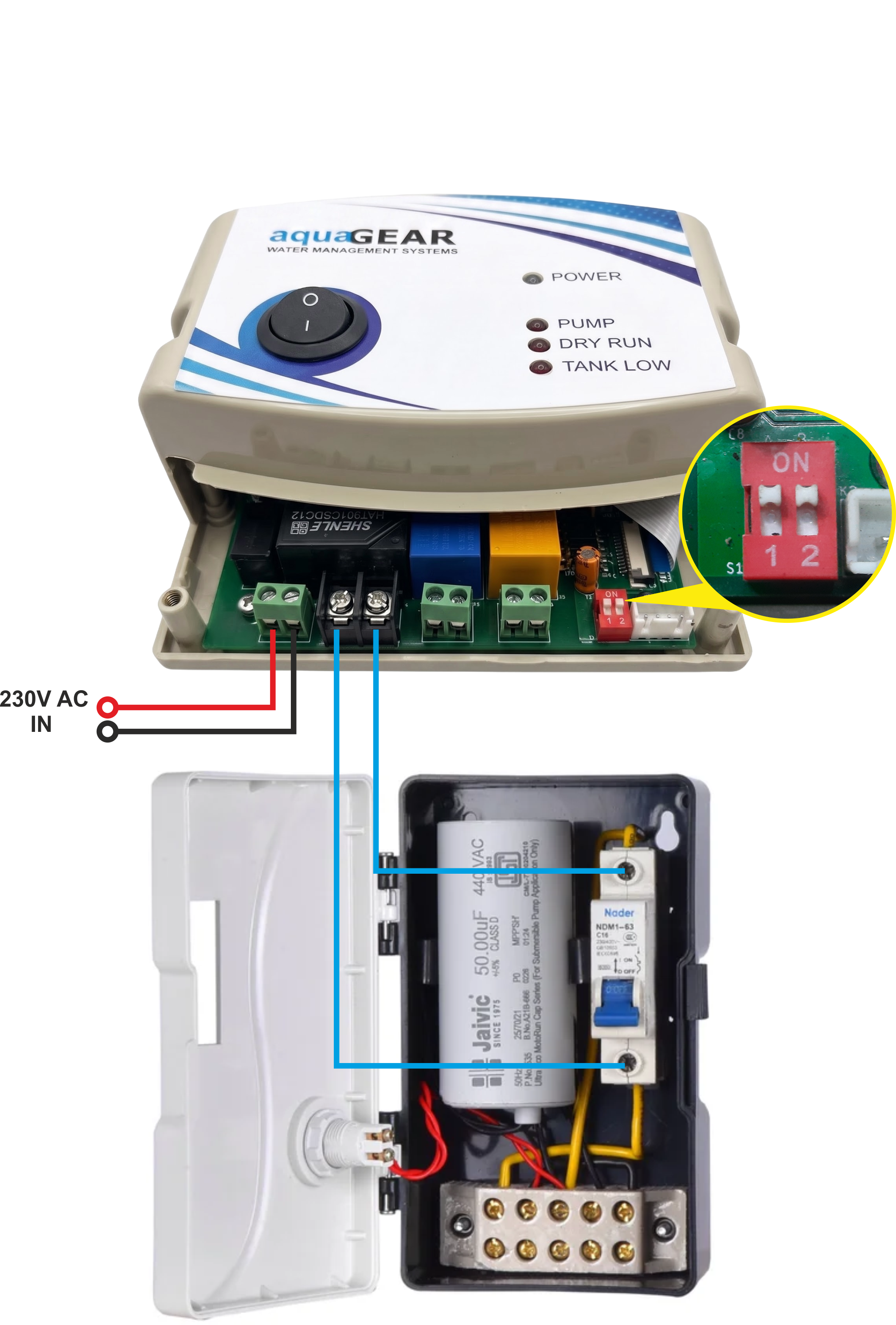
For deep-well submersible borehole pumps equipped with an external run capacitor and MCB control box. The built-in 30A Start Relay 1 (T3, T4) directly controls the motor load. Well-suited for 0.5 HP, 1.0 HP, and 1.5 HP pumps.
Wiring Connections:
- Connect 230V AC Mains Phase to Station T1 and Mains Neutral to Station T2 terminals to power the unit.
- Connect 230V AC Mains Neutral directly to the Capacitor Control Box Neutral terminal (and common with motor neutral).
- Connect Station Start Relay 1 terminals T3 & T4 (Normally Open - NO, 30A) in parallel across the Capacitor Box MCB switch (Phase input to Phase output) to directly power the motor load.
- Keep the Control Box MCB switched OFF for continuous automated operation.
- Confirm Selection switch setting: Switch 1 is ON, Switch 2 is ON.
TYPE 5: MULTI CAPACITOR MCB TYPE SUBMERSIBLE PANEL

Wiring Connections:
- Connect 230V AC Mains Phase to Station T1 and Mains Neutral to Station T2 terminals to power the unit.
- Connect Station Start Relay 1 terminals T3 & T4 (Normally Open - NO, 30A) in parallel across the panel MCB switch (top incoming phase terminal and bottom outgoing terminal) to control continuous motor power.
- Connect Station Start Relay 2 terminals T7 & T8 (Normally Open - NO, 7A) in parallel across the panel door-mounted Green START push-button contacts to provide the initial start capacitor pulse.
- Terminals T5 & T6 (Stop Relay) remain unused for this panel configuration (stopping is automatically handled when Start Relay 1 opens).
- Keep the panel MCB switched OFF for continuous automated operation.
- Confirm Selection switch setting: Switch 1 is OFF, Switch 2 is OFF.
Upgrade to Intelligent Water Management
Fill out the quick enquiry form below for pricing, installation feasibility, dealership opportunities, or custom engineering requirements. If you require any customization—such as multi-tank setups, specialized pump starter panel integrations, extended wireless communication range, or tailored operational logic—our technical engineering team will evaluate your specifications and get back to you promptly.
Need Immediate Assistance?
Speak directly with an AGUAGEAR application engineer for instant advice or on-site installation booking.